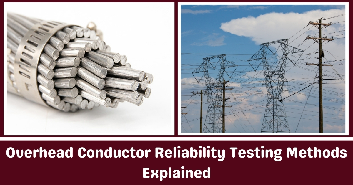
Overhead conductors are critical components in the transmission and distribution of electrical power. They are constantly exposed to harsh environmental conditions like extreme temperatures, high winds, moisture, and mechanical stresses.
Over time, these factors can degrade the performance of conductors, leading to higher energy losses, sagging, or even catastrophic failures.
To ensure the safety, efficiency, and longevity of power systems, reliability testing of overhead conductors is not just recommended it is essential.
Testing provides hard, actionable data that helps utilities and engineers understand how conductors perform under real-world stressors.
Instead of relying on assumptions or historical performance alone, structured testing identifies potential weaknesses before they become major issues.
This allows companies to plan maintenance schedules, improve material selection, and make smarter investment decisions based on proven reliability data.
Without rigorous testing, overhead conductors can become a hidden risk to the power grid a risk that only shows itself when it’s too late.
In this guide, we will explain the major overhead conductor reliability testing methods, how they are performed, and why each one matters.
Overhead conductors are constantly subjected to various mechanical, thermal, and environmental stresses during their lifetime.
Testing is necessary to ensure these conductors can operate reliably under different conditions without premature failure.
Without testing, there is a risk of outages, safety hazards, and costly maintenance. Testing also verifies that new designs or materials meet industry standards before full-scale deployment.
Overall, testing supports system reliability, operational safety, and effective maintenance planning.
Testing of overhead conductors can be divided into two broad categories: field testing and laboratory testing.
Field testing evaluates conductors under real operating conditions, often identifying issues caused by installation practices, environmental exposure, or long-term aging.
Laboratory testing, on the other hand, focuses on controlled experiments to measure specific material or mechanical properties. Both methods are critical.
Field testing offers real-world validation, while laboratory testing isolates specific variables for a detailed understanding of conductor behavior.
Tensile strength testing measures the maximum amount of stress a conductor can withstand when stretched before it breaks. This test is critical because overhead conductors are under constant tension.
To perform the test, a sample is secured between two clamps in a tensile testing machine. The machine gradually applies force until the sample fractures.
The breaking force is recorded, and the tensile strength is calculated by dividing the force by the original cross-sectional area of the conductor.
High tensile strength is important for maintaining line integrity, especially in areas subject to high wind or ice loads.
Creep testing evaluates the long-term deformation of a conductor under constant mechanical load. Conductors tend to stretch gradually over time under the tension of their own weight and environmental forces.
Excessive creep can increase sag, which reduces ground clearance and compromises safety. In a typical creep test, a conductor sample is loaded with a sustained tension and maintained under controlled temperature conditions.
Measurements of elongation are taken over time, often over thousands of hours. The data helps predict the long-term sag behavior of conductors and informs sag-tension calculations used in line design.
Overhead conductors are exposed to moisture, salt, pollutants, and other corrosive agents, particularly in coastal and industrial environments.
Corrosion resistance testing determines how well conductor materials withstand these conditions.
Laboratory methods typically involve exposing samples to accelerated environmental conditions such as salt fog, humidity chambers, or chemical sprays.
After exposure, the samples are inspected for surface pitting, material loss, or changes in mechanical properties. Conductors with strong corrosion resistance have longer service lives and lower maintenance requirements.
Thermal cycling testing simulates the daily and seasonal temperature variations that conductors experience in service. Expansion and contraction from temperature changes can cause fatigue, loosen fittings, and accelerate material degradation.
In thermal cycling tests, conductor samples are subjected to repeated heating and cooling cycles, often between extreme temperature limits.
The cycles may number in the thousands to represent years of operation. After testing, samples are inspected for mechanical damage, loosening of strands, or reduction in mechanical properties.
Good performance in thermal cycling tests is essential for conductors installed in regions with large temperature fluctuations.
Electrical resistance testing measures the ability of a conductor to carry current efficiently. High resistance results in higher energy losses and heating, reducing system efficiency.
In this test, a known current is passed through the conductor, and the resulting voltage drop is measured. Resistance is then calculated using Ohm’s Law.
Testing may be done at different temperatures to understand how resistance changes with thermal expansion.
Conductors with low, stable resistance are preferred, especially for long transmission lines where efficiency is critical.
Wind-induced vibrations can cause fatigue damage to overhead conductors, especially near suspension clamps. This phenomenon, known as aeolian vibration, can lead to strand breakage and eventual failure.
Vibration fatigue testing simulates these conditions by subjecting a conductor sample to cyclic mechanical movements over a long period.
Test setups typically include a vibration generator and a counterweight to replicate natural frequencies experienced in the field.
After testing, samples are examined for signs of strand fretting, broken wires, or loss of mechanical properties. Successful performance in vibration fatigue testing ensures the conductor’s durability in windy conditions.
The sag of an overhead conductor changes with temperature because of thermal expansion. Excessive sag can violate clearance requirements and lead to dangerous situations.
Sag-temperature relationship testing determines how much a conductor will sag as it heats up under electrical load or ambient temperature changes.
In this test, a conductor is tensioned between two points under controlled conditions, then heated while sag measurements are recorded at various temperatures.
The data is used to create sag-tension charts that guide line design and operation. Accurate sag prediction ensures compliance with clearance regulations and system safety.
Short-circuit events generate extremely high currents that can heat conductors rapidly, causing thermal and mechanical stresses.
Short-circuit testing evaluates a conductor’s ability to withstand these extreme conditions without permanent damage.
In the test, a high-magnitude current is passed through the conductor for a few cycles, simulating a real fault event. The conductor is then inspected for deformation, strand separation, or mechanical weakening.
Conductors that pass short-circuit tests demonstrate resilience against sudden fault conditions and maintain mechanical integrity after the event.
Conductor materials, particularly protective coatings or composite cores, are vulnerable to ultraviolet (UV) radiation and moisture over time.
Accelerated aging tests expose conductor samples to intense UV light, humidity, and sometimes thermal cycling simultaneously to simulate years of environmental exposure in a shorter period.
The tests evaluate changes in physical appearance, mechanical strength, electrical performance, and overall material stability.
Accelerated aging testing ensures that conductor materials retain their essential properties even after prolonged outdoor service, reducing the likelihood of unexpected failures.
Reliability testing of overhead conductors is not just a technical requirement it’s a fundamental step toward ensuring the long-term safety and efficiency of power transmission systems.
Each test serves a specific purpose, from understanding how a conductor handles stress and temperature to evaluating its resistance to corrosion, vibration, and aging.
When used together, these testing methods provide a complete picture of a conductor’s performance under real-world operating conditions.
As power demand increases and aging infrastructure faces new challenges, utilities and engineers must rely on accurate testing data to make informed decisions.
These tests help minimize the risk of unexpected failures, reduce maintenance costs, and support better system design.
Whether in the lab or in the field, reliability testing is the bridge between manufacturer claims and real-world durability.
Investing time and resources into comprehensive testing up front helps avoid costly downtime and system disruptions later. It’s not about over-engineering it’s about building trust in the components that keep the lights on.
With a clear understanding of these testing methods, stakeholders can make smarter, safer choices when selecting and deploying overhead conductors.