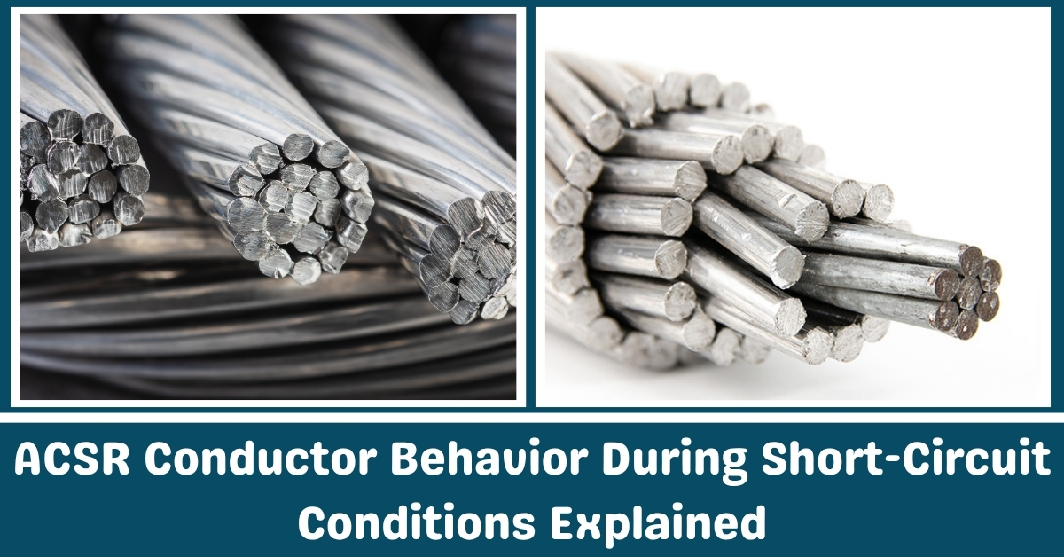
In power transmission systems, reliability is paramount, and ACSR (Aluminum Conductor Steel Reinforced) conductors are at the heart of that mission.
Known for their high tensile strength and efficient current-carrying capacity, these conductors form the backbone of overhead lines across the globe.
However, despite their robust construction, ACSR conductors face their greatest challenge not during regular operation but in the critical moments of a short-circuit.
Short-circuit faults can release intense electrical energy in milliseconds, pushing ACSR conductors to their physical and thermal limits.
Temperatures can spike within fractions of a second, mechanical forces can cause sudden movement, and the consequences if not accounted for can lead to system failure or safety hazards.
Understanding how these conductors react under such conditions is essential for electrical engineers, utility planners, and system operators.
From the conductor’s thermal rise to mechanical strain, and from sagging risks to failure thresholds, knowing the science behind these reactions helps in designing fault-resilient transmission lines.
Real data, standard-based guidelines, and practical field examples all contribute to this critical understanding.
In this guide, we will explain how ACSR conductors behave during short-circuit conditions and what it means for power system safety and performance.
A short-circuit is an unintentional, low-impedance connection between two points in an electrical circuit, often involving conductors at different voltages. In transmission systems, it represents one of the most severe electrical faults.
When a short-circuit occurs, electrical current deviates from its intended path, flowing through the unintended route with very little resistance.
As a result, the current level surges far beyond normal operating values, sometimes by a factor of 10 to 30 times the rated current, depending on system impedance and source capacity.
The problem with short-circuits lies in their sudden and intense impact. This extreme current generates massive thermal energy almost instantly, which can overheat conductors, damage insulation, and cause mechanical strain on equipment.
The energy released in a short-circuit doesn’t give the system much time to react usually less than a second so the design and materials must be capable of handling such transient conditions.
For ACSR conductors, short-circuits are particularly important because these events test their thermal and mechanical endurance.
If not properly rated or if operating too close to capacity, the conductors can suffer overheating, mechanical deformation, or even failure.
That’s why understanding their behavior under fault conditions is not optional—it’s critical for system stability, long-term durability, and personnel safety.
Not all short-circuits are the same. In overhead transmission lines, faults can take different forms depending on how many conductors are involved and how they connect to ground.
The most common types of short-circuit faults in transmission networks include single line-to-ground, line-to-line, double line-to-ground, and three-phase faults.
A single line-to-ground fault occurs when one phase conductor makes contact with the earth or with a grounded object such as a pole or tree.
This is the most common type of fault in overhead systems and is often caused by environmental factors like lightning, tree branches, or conductor movement.
Line-to-line faults involve direct contact between two conductors. This kind of fault is less frequent but can produce higher fault currents, especially if the contact is sustained.
A double line-to-ground fault involves two phase conductors and ground, which increases fault current magnitude and complexity.
The most severe and symmetrical fault is the three-phase short-circuit. In this scenario, all three conductors are simultaneously shorted together or to ground.
This is often used in system design studies because it produces the highest possible fault current. Protection systems are typically set to detect and respond to this worst-case scenario.
Each fault type has a different effect on the ACSR conductor in terms of thermal loading and mechanical stress.
System design must take into account the worst-case type and duration to ensure that the conductors and supporting equipment can withstand the stress without damage.
When a short-circuit occurs, one of the first and most dangerous effects on ACSR conductors is the rapid temperature rise due to the large current flow.
Because aluminum, which forms the outer layer of an ACSR conductor, has a relatively low melting point, it is more vulnerable to quick heating than other metallic conductors.
During a short-circuit event, the aluminum strands can reach extremely high temperatures in just a fraction of a second.
Under normal conditions, the conductor may operate at around 75 to 90 degrees Celsius.
However, in a short-circuit event, the conductor can temperatures reach of 200, 400, or even up to 600 degrees Celsius depending on the fault current and its duration.
This thermal shock occurs so quickly that it doesn’t allow heat to dissipate, leading to steep temperature gradients within the conductor.
The outer aluminum strands heat up faster than the steel core. This causes expansion in the outer layer while the inner steel remains relatively cooler. Such unequal expansion creates internal stresses within the conductor.
If the fault duration is prolonged, even slightly, the aluminum can begin to soften or deform. In extreme cases, the aluminum may melt, especially if the temperature approaches its melting point of around 660 degrees Celsius.
What makes this even more critical is the cumulative effect of repeated faults.
Even if a short-circuit doesn’t immediately damage the conductor, repeated exposure to high temperatures can lead to long-term deterioration of the aluminum and increased sag due to annealing.
This is why thermal performance under short-circuit conditions is one of the key design criteria for ACSR in high-voltage systems.
Short-circuits not only produce thermal stress but also generate strong mechanical forces on conductors. These forces are the result of electromagnetic interaction between current-carrying conductors, particularly when the fault current reaches several thousand amperes.
The strength of the mechanical force increases with the square of the current, making high-current faults especially violent.
In multi-phase lines, when current flows in opposite directions through nearby conductors, they experience repulsive forces. These sudden forces can cause the conductors to move rapidly or even slap into each other.
The conductor movement is not only a result of the electromagnetic force but also from the physical expansion due to thermal effects.
Such mechanical disturbances can lead to several consequences. First, conductor movement can cause contact with adjacent phases or structures, leading to secondary faults.
Second, the movement may damage insulators or connectors due to the jerking force. Third, in extreme cases, the mechanical shock can cause fatigue in the conductor strands or at the points where the conductor is clamped.
Another factor to consider is the vibration introduced during the fault. Even brief but violent oscillations can weaken mechanical fittings over time.
This mechanical vulnerability highlights the importance of designing transmission lines with appropriate spacing, bracing, and mechanical damping to limit conductor movement during fault conditions.
The amount of heat generated in a conductor during a short-circuit is directly related to both the magnitude of the current and the duration of the fault.
Even a high-magnitude current may not cause damage if the protection system clears the fault quickly. Conversely, even a moderately high current can cause significant damage if it persists longer than the conductor’s thermal capacity allows.
This time-current relationship is a crucial aspect of fault analysis and conductor selection. ACSR conductors are rated for specific short-circuit current levels over a defined duration typically one or three seconds.
Beyond this time, the conductor’s temperature can exceed safe limits. For example, a conductor may be rated to handle 13,000 amps for one second, but only 9,000 amps for three seconds.
The limiting factor is usually the temperature at which the aluminum strands begin to lose their mechanical properties. Most ACSR conductors are designed to withstand temperatures emergency up to 250 degrees Celsius.
However, during a fault, the maximum temperature can be allowed to reach around 500 to 600 degrees Celsius—provided this occurs only once or infrequently and does not cause melting.
If the system’s protection relay settings are not optimized, or if fault clearing takes too long, these limits can be exceeded.
This can lead to permanent damage such as annealing of the aluminum, which reduces its strength and increases sag, or damage to hardware like spacers and clamps.
That’s why quick fault detection and isolation are essential to maintain conductor integrity.
One of the most dangerous outcomes of a short-circuit is the potential for conductor melting and sagging. As mentioned earlier, the aluminum strands of an ACSR conductor can reach high temperatures in a short time.
If the temperature reaches or exceeds the melting point of aluminum, even briefly, the strands can soften or melt.
Melting isn’t always uniform across the conductor. In some cases, partial melting occurs in localized hot spots, particularly near clamps or joints where resistance is slightly higher.
These weak points may become brittle after cooling or may fail under mechanical load. Once this happens, the structural strength of the conductor is compromised, increasing the likelihood of a break or collapse.
Even if the conductor does not melt, elevated temperatures can cause permanent elongation of the aluminum.
This leads to increased sag. In a tightly tensioned span, any extra sag can reduce the clearance between the conductor and ground or other objects.
If the clearance drops below regulatory limits, it can cause flashovers, tree contact, or violations of safety codes.
The steel core of the ACSR helps resist sag to an extent, but prolonged heating still affects the overall performance.
After a short-circuit event, conductors should be inspected for signs of sagging, stretching, or discoloration. If sag exceeds allowable limits, the conductor may need to be retensioned or replaced.
To ensure ACSR conductors perform reliably during short-circuits, international standards provide design frameworks and testing procedures. Two of the most relevant standards are IEC 60949 and IEEE 738 .
IEC 60949 provides guidelines for calculating the permissible short-circuit current in power conductors. It considers factors like conductor cross-sectional area, material properties, fault duration, and temperature rise.
These calculations ensure that the chosen conductor can handle anticipated fault currents without exceeding thermal limits.
IEEE 738 focuses more on the thermal behavior of overhead conductors, including ACSR. It provides methods to determine conductor temperature under steady-state and transient (short-circuit) conditions.
This standard is often used by utilities to simulate conductor temperature rise and confirm that the thermal response stays within allowable ranges.
In addition to thermal criteria, mechanical aspects are addressed in standards like IEC 60826 , which covers mechanical loading for overhead lines.
This includes guidelines for handling wind, ice, and fault-induced mechanical forces.
When designing a transmission line, engineers must consider the worst-case short-circuit current and duration, then select ACSR conductors and associated hardware that meet or exceed these values.
Protection systems must be coordinated to clear faults within the timeframes defined in the thermal ratings. It is also recommended to leave a margin between expected fault levels and conductor capacity to account for uncertainties or changes in system configuration.
Proper design, testing, and regular inspection form a three-layer defense against the damaging effects of short-circuits on ACSR conductors.
Adhering to international standards ensures the system can handle extreme conditions without compromising performance or safety.
Short-circuit events place extreme thermal and mechanical stress on ACSR conductors within a matter of milliseconds. These faults are not just theoretical risks they are real operational challenges that demand proper planning and system design.
As we’ve explored, It experience rapid temperature rise, possible deformation, and high electromagnetic forces during such conditions.
If not properly accounted for, these effects can lead to sagging, melting, or even mechanical failure.
The key to maintaining system reliability lies in understanding how conductors behave under fault, selecting the correct conductor size and configuration, and ensuring that fault clearing systems act within safe thermal limits.
Following standards such as IEC 60949 and IEEE 738 helps engineers accurately assess the thermal capacity and mechanical strength required for short-circuit scenarios.
Ultimately, preparing for short-circuit behavior is about more than protecting equipment—it’s about preserving system stability, reducing downtime, and maintaining safety.
Whether you’re designing a new transmission line or assessing an existing one, integrating fault-resilient planning for ACSR conductors is a crucial part of reliable power system engineering.